7 DOF Mobile Robot Simulation
and Kinematic Analysis using ROS
Introduction
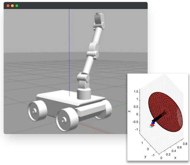
In this project, I collaborated to work on the simulation and analysis of a 7 Degree of Freedom (DOF) Mobile Robot in Gazebo, aiming to facilitate real-world manipulation tasks. After defining and modelling the robot’s physical characteristics the project encompassed a comprehensive kinematic analysis, covering position, workspace, singularity, and stiffness analysis for the robot manipulator. Additionally, a virtual environment was created to simulate a sample pick-and-place task, utilizing the calculated parameters. This simulation and analysis serve as crucial steps in understanding and optimizing the robot’s performance for practical applications.
Methodology
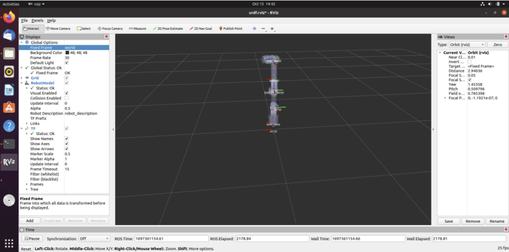
Manipulator Arm and Mobile Robot: The robotic manipulator arm contained five revolute joints named arm base, bicep, bottom wrist,
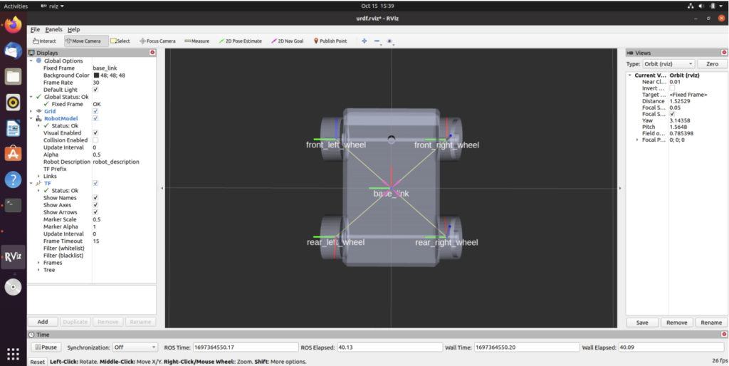
elbow and top wrist (5-dof). The mobile robot was a four-wheeled robotic platform designed for mobility and autonomous navigation having five different coordinate systems namely front right wheel, rear right wheel, front left wheel, rear left wheel and base link. The mobile robot constituted of a few key components like: the chassis, wheels, motors, sensors(Lidar, camera, ultrasonic sensors, encoders, IMUs etc.) The mobile base has only 2 degrees of freedom: a translation along the x axis and rotation along the z axis. The robot cannot move instantaneously in the y axis due to the fixed steering wheel assumption. Since the robot moves only on the ground, it cannot translate in the z axis as well in ideal cases. The Kinematic Analysis of the manipulator arm and mobile platform were conducted according to the selected DH-Parameters. The codes for the the kinematics can be found here: (i) Manipulator Arm (ii) Mobile Robot.
After the kinematics, the velocity analysis was done for the robot manipulator and the codes for the manipulability and stiffness analysis can be found below:
% ------------------------------------- PLOTTING MANIPULABILITY -------------------------------------


link1_pos_=H_m_1_symb(0.1);
link1_pos=(link1_pos_(1:3,4));
link2_pos_=H_m_2_symb(0.1,0.1);
link2_pos=(link2_pos_(1:3,4));
link3_pos_=H_m_3_symb(0.1,0.1,0.1);
link3_pos=(link3_pos_(1:3,4));
link4_pos_=H_m_4_symb(0.1,0.1,0.1,0.1);
link4_pos=(link4_pos_(1:3,4));
link5_pos_=H_m_5_symb(0.1,0.1,0.1,0.1,0.1);
link5_pos=(link5_pos_(1:3,4));

%%
% ------------ 1. TRANSLATIONAL MANIPULABILITY ELLIPSOID -----------------

figure(1001)
mw=5;lw=10;
lw1=0.5;
syms x y z
x_d=[x-link5_pos(1);y-link5_pos(2);z-link5_pos(3)];

% lw=1;
E_V=transpose(x_d)*pinv(p(1:3,:)*transpose(p(1:3,:)))*x_d-1;
fimplicit3(E_V,'-b','LineWidth',lw1,'FaceAlpha',.5) %%%% velocity manipulability Ellipse
hold on
E_VC=transpose(x_d)*pinv(q(1:3,:)*transpose(q(1:3,:)))*x_d-1;
fimplicit3(E_VC,'-r','LineWidth',lw1,'FaceAlpha',.1) %%%% velocity manipulability Ellipse

% plot3(0,0,0,'og','LineWidth',mw) %%% ground marker
plot3([0 link1_pos(1)], [0 link1_pos(2)],[0 link1_pos(3)],'-c','LineWidth',lw) %%% link1
plot3([link1_pos(1) link2_pos(1)], [link1_pos(2) link2_pos(2)],[link1_pos(3) link2_pos(3)],'-r','LineWidth',lw) %%% link2
plot3([link2_pos(1) link3_pos(1)],[link2_pos(2) link3_pos(2)],[link2_pos(3) link3_pos(3)],'-g','LineWidth',lw) %%%% link3
plot3([link3_pos(1) link4_pos(1)],[link3_pos(2) link4_pos(2)],[link3_pos(3) link4_pos(3)],'-b','LineWidth',lw) %%%% link4
plot3([link4_pos(1) link5_pos(1)],[link4_pos(2) link5_pos(2)],[link4_pos(3) link5_pos(3)],'-k','LineWidth',lw) %%%% link5
xlabel('x');
ylabel('y');
zlabel('z');
title('Linear Velocity manipulability')
% xlim([-0.5 4]);
% ylim([-2.5 2]);
grid minor;
% axis square ;
legend('Velocity Manipulability Ellipsoid','Combined Velocity Manipulability Ellipsoid','link1', 'link2', 'link3', 'link4', 'link5');


%%
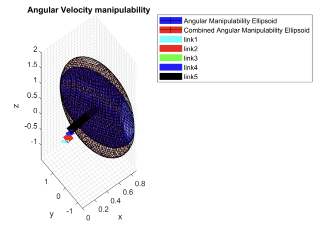
% ------------ 2. ANGULAR MANIPULABILITY ELLIPSOID -----------------

figure(1002)

E_V=transpose(x_d)*pinv(p(4:6,:)*transpose(p(4:6,:)))*x_d-1;
fimplicit3(E_V,'-b','LineWidth',lw1,'FaceAlpha',.5) %%%% velocity manipulability Ellipse
hold on
E_VC=transpose(x_d)*pinv(q(4:6,:)*transpose(q(4:6,:)))*x_d-1;
fimplicit3(E_VC,'-r','LineWidth',lw1,'FaceAlpha',0.1) %%%% velocity manipulability Ellipse
mw=5;lw=10;
lw1=0.5;

% plot3(0,0,0,'og','LineWidth',mw) %%% ground marker
plot3([0 link1_pos(1)], [0 link1_pos(2)],[0 link1_pos(3)],'-c','LineWidth',lw) %%% link1
plot3([link1_pos(1) link2_pos(1)], [link1_pos(2) link2_pos(2)],[link1_pos(3) link2_pos(3)],'-r','LineWidth',lw) %%% link2
plot3([link2_pos(1) link3_pos(1)],[link2_pos(2) link3_pos(2)],[link2_pos(3) link3_pos(3)],'-g','LineWidth',lw) %%%% link3
plot3([link3_pos(1) link4_pos(1)],[link3_pos(2) link4_pos(2)],[link3_pos(3) link4_pos(3)],'-b','LineWidth',lw) %%%% link4
plot3([link4_pos(1) link5_pos(1)],[link4_pos(2) link5_pos(2)],[link4_pos(3) link5_pos(3)],'-k','LineWidth',lw) %%%% link5
xlabel('x');
ylabel('y');
zlabel('z');
title('Angular Velocity manipulability')
% xlim([-0.5 4]);
% ylim([-2.5 2]);
grid minor
% axis square ;
legend('Angular Manipulability Ellipsoid','Combined Angular Manipulability Ellipsoid','link1', 'link2', 'link3', 'link4', 'link5');


%%
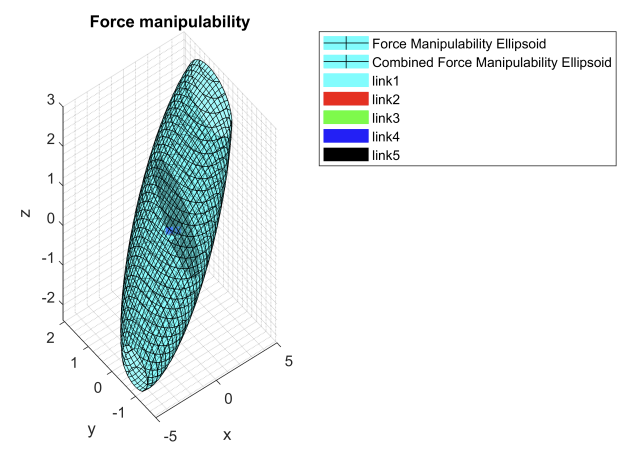
% ------------ 3. FORCE MANIPULABILITY ELLIPSOID -----------------

syms fx fy fz

f=[fx-link5_pos(1); fy-link5_pos(2); fz-link5_pos(3)];
figure(2001)
E_F=transpose(f)*(p(1:3,:)*p(1:3,:)')*f-1;
fimplicit3(E_F,'-c','LineWidth',lw1,'FaceAlpha',.5) %%%% Force Manipulability Ellipse
hold on
E_FC=transpose(f)*(q(1:3,:)*q(1:3,:)')*f-1;
fimplicit3(E_FC,'-c','LineWidth',lw1,'FaceAlpha',.1) %%%% Force Manipulability Ellipse
mw=5;lw=10;

% plot3(0,0,0,'og','LineWidth',mw) %%% ground marker
plot3([0 link1_pos(1)], [0 link1_pos(2)],[0 link1_pos(3)],'-c','LineWidth',lw) %%% link1
plot3([link1_pos(1) link2_pos(1)], [link1_pos(2) link2_pos(2)],[link1_pos(3) link2_pos(3)],'-r','LineWidth',lw) %%% link2
plot3([link2_pos(1) link3_pos(1)],[link2_pos(2) link3_pos(2)],[link2_pos(3) link3_pos(3)],'-g','LineWidth',lw) %%%% link3
plot3([link3_pos(1) link4_pos(1)],[link3_pos(2) link4_pos(2)],[link3_pos(3) link4_pos(3)],'-b','LineWidth',lw) %%%% link4
plot3([link4_pos(1) link5_pos(1)],[link4_pos(2) link5_pos(2)],[link4_pos(3) link5_pos(3)],'-k','LineWidth',lw) %%%% link5
xlabel('x');
ylabel('y');
zlabel('z');
title('Force manipulability')
% xlim([-0.5 4]);
% ylim([-2.5 2]);
grid minor
% axis square ;
legend('Force Manipulability Ellipsoid','Combined Force Manipulability Ellipsoid','link1', 'link2', 'link3', 'link4', 'link5');


%%
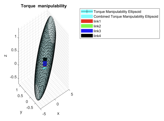
% ------------ 4. MOMENT MANIPULABILITY ELLIPSOID -----------------

figure(2002)
lw1=0.5;

E_MC=transpose(f)*(p(4:6,:)*p(4:6,:)')*f-1;
fimplicit3(E_MC,'-c','LineWidth',lw1,'FaceAlpha',.1) %%%% Force Manipulability Ellipse
mw=5;lw=10;
hold on

% plot3(0,0,0,'og','LineWidth',mw) %%% ground marker
plot3([0 link1_pos(1)], [0 link1_pos(2)],[0 link1_pos(3)],'-c','LineWidth',lw) %%% link1
plot3([link1_pos(1) link2_pos(1)], [link1_pos(2) link2_pos(2)],[link1_pos(3) link2_pos(3)],'-r','LineWidth',lw) %%% link2
plot3([link2_pos(1) link3_pos(1)],[link2_pos(2) link3_pos(2)],[link2_pos(3) link3_pos(3)],'-g','LineWidth',lw) %%%% link3
plot3([link3_pos(1) link4_pos(1)],[link3_pos(2) link4_pos(2)],[link3_pos(3) link4_pos(3)],'-b','LineWidth',lw) %%%% link4
plot3([link4_pos(1) link5_pos(1)],[link4_pos(2) link5_pos(2)],[link4_pos(3) link5_pos(3)],'-k','LineWidth',lw) %%%% link5
xlabel('x');
ylabel('y');
zlabel('z');
title('Torque manipulability')
% xlim([-0.5 4]);
% ylim([-2.5 2]);
grid minor
% axis square ;
legend('Torque Manipulability Ellipsoid','Combined Torque Manipulability Ellipsoid','link1', 'link2', 'link3', 'link4', 'link5');
% ------------------------------------- STIFFNESS ANALYSIS -------------------------------------

syms theta1 theta2 theta3 theta4 theta5
J_manipulator=J_manipulator_symb(0.1,0.1,0.1,0.1,0.1)


%%
% ------------ 1. JOINT STIFFNESS ANALYSIS: Kq -----------------

%%% Lets assume a symmetric and cosntant joint stiffness matrix as
vv=[100 100 100 100 100]; %%% defined diagonal just to take decoupled kq
 kq=diag(vv);


%%
% ------------ 2. GEOMETRIC STIFFNESS ANALYSIS: Kg -----------------

a=1;
Fext=[a; a; a; 0; 0; 0];
% syms theta1 theta2 theta3 theta4 theta5 real
% t=[theta1; theta2; theta3; theta4; theta5];
% kg=zeros(5,5);
kg1=(diff(transpose(J_manipulator),theta1))*Fext;
kg2=(diff(transpose(J_manipulator),theta2))*Fext;
kg3=(diff(transpose(J_manipulator),theta3))*Fext;
kg4=(diff(transpose(J_manipulator),theta4))*Fext;
kg5=(diff(transpose(J_manipulator),theta5))*Fext;
kg=[kg1 kg2 kg3 kg4 kg5];
%%
% singularValues=sqrt(J_combined*transpose(J_combined));
% singularValues1=simplify(rref(J_combined))


%%
% ------------ 3. TASKSPACE STIFFNESS ANALYSIS: Kx -----------------

Kx=vpa(pinv(transpose(J_manipulator))*(kq-kg)*pinv(J_manipulator),3)
eig(Kx(4:6,:)*Kx(4:6,:)')


%%
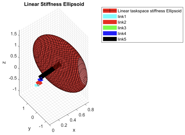
% ------------------------------------- TRANSLATIONAL TASKSPACE STIFFNESS ELLIPSOID -------------------------------------

figure(3001)
K_X=transpose(x_d)*pinv(Kx(1:3,:)*transpose(Kx(1:3,:)))*x_d-1;

fimplicit3(E_V,'-r','LineWidth',lw1,'FaceAlpha',.5) %%%% velocity manipulability Ellipse
mw=5;lw=10;
lw1=0.5;
hold on
% plot3(0,0,0,'og','LineWidth',mw) %%% ground marker
plot3([0 link1_pos(1)], [0 link1_pos(2)],[0 link1_pos(3)],'-c','LineWidth',lw) %%% link1
plot3([link1_pos(1) link2_pos(1)], [link1_pos(2) link2_pos(2)],[link1_pos(3) link2_pos(3)],'-r','LineWidth',lw) %%% link2
plot3([link2_pos(1) link3_pos(1)],[link2_pos(2) link3_pos(2)],[link2_pos(3) link3_pos(3)],'-g','LineWidth',lw) %%%% link3
plot3([link3_pos(1) link4_pos(1)],[link3_pos(2) link4_pos(2)],[link3_pos(3) link4_pos(3)],'-b','LineWidth',lw) %%%% link4
plot3([link4_pos(1) link5_pos(1)],[link4_pos(2) link5_pos(2)],[link4_pos(3) link5_pos(3)],'-k','LineWidth',lw) %%%% link5
xlabel('x');
ylabel('y');
zlabel('z');
title('Linear Stiffness Ellipsoid')
% xlim([-0.5 4]);
% ylim([-2.5 2]);
grid minor
% axis square ;
legend('Linear taskspace stiffness Ellipsoid','link1','link2','link3','link4','link5')


%%
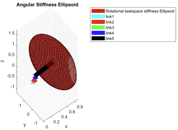
% ------------------------------------- ANGULAR TASKSPACE STIFFNESS ELLIPSOID -------------------------------------

figure(3002)
K_T=transpose(x_d)*pinv(Kx(4:6,:)*transpose(Kx(4:6,:)))*x_d-1;

fimplicit3(E_V,'-r','LineWidth',lw1,'FaceAlpha',.5) %%%% velocity manipulability Ellipse
mw=5;lw=10;
lw1=0.5;
hold on
% plot3(0,0,0,'og','LineWidth',mw) %%% ground marker
plot3([0 link1_pos(1)], [0 link1_pos(2)],[0 link1_pos(3)],'-c','LineWidth',lw) %%% link1
plot3([link1_pos(1) link2_pos(1)], [link1_pos(2) link2_pos(2)],[link1_pos(3) link2_pos(3)],'-r','LineWidth',lw) %%% link2
plot3([link2_pos(1) link3_pos(1)],[link2_pos(2) link3_pos(2)],[link2_pos(3) link3_pos(3)],'-g','LineWidth',lw) %%%% link3
plot3([link3_pos(1) link4_pos(1)],[link3_pos(2) link4_pos(2)],[link3_pos(3) link4_pos(3)],'-b','LineWidth',lw) %%%% link4
plot3([link4_pos(1) link5_pos(1)],[link4_pos(2) link5_pos(2)],[link4_pos(3) link5_pos(3)],'-k','LineWidth',lw) %%%% link5
xlabel('x');
ylabel('y');
zlabel('z');
title('Angular Stiffness Ellipsoid')
% xlim([-0.5 4]);
% ylim([-2.5 2]);
grid minor
% axis square ;
legend('Rotational taskspace stiffness Ellipsoid','link1','link2','link3','link4','link5')
Results & Discussion
The results of the simulation and analysis for the 7 DOF Mobile Robot in Gazebo are presented below. The position analysis provided a detailed understanding of the robot’s end-effector movements within its workspace, outlining its reach and limitations. Workspace analysis further contributed to identifying optimal regions for effective task execution. Singularity analysis played a significant role in highlighting critical points where the robot’s manipulability is compromised, allowing for strategic adjustments in its design or operation to mitigate such issues. The stiffness analysis offered valuable data on the robot’s structural integrity and its ability to withstand external forces during manipulation tasks.
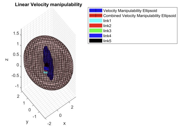
The velocity manipulability ellipsoids along with the force, torque, and stiffness ellipsoids for the robot can be found below:
Simulation task: Video
Conclusion & Future Work
In conclusion, the simulation and analysis of the 7 DOF Mobile Robot in Gazebo have provided valuable insights into its kinematic performance and potential real-world applications. The comprehensive understanding of its workspace, singularity points, and stiffness characteristics is fundamental for optimizing its design and operation. The successful execution of a pick-and-place task in the virtual environment demonstrates the robot’s practical utility. For future work, the project could delve into refining control algorithms to enhance the robot’s autonomy and adaptability in dynamic environments. Incorporating additional sensors for improved perception and developing strategies to handle unforeseen challenges would further contribute to the robot’s versatility. Moreover, experimental validation of the simulated results in a physical setup would be essential to confirm the practical feasibility of the robot’s manipulative capabilities.
Additional Documents
–
Guide: – | Collaborators: Randheer Singh, Dhyey Shah