Smart Shoe for Wireless
Ground Reaction Force
Prediction using a
Deep Neural Network
Introduction
The primary objective of this research study is to showcase the implementation of a wireless and portable system designed for real-time prediction of Ground Reaction Forces (GRF) through the application of on-board machine learning techniques. I developed a novel Smart Shoe with air bladder coils within the insoles, connected to differential pressure sensors to wirelessly monitor Ground Reaction Forces (GRF), temporal gait parameters and CoP in real-time using a custom-trained Convolutional Neural Network (CNN). The system was validated against force plates and the VICON motion capture system (gold standards) offering assessment and feedback to the participants.
Methodology
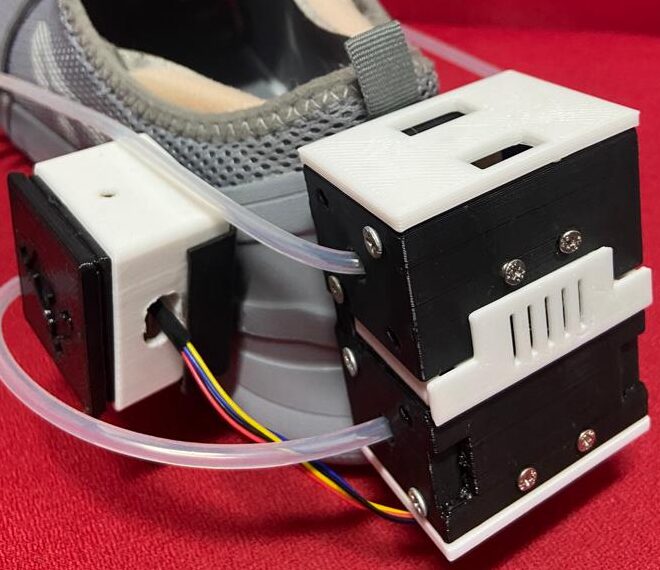
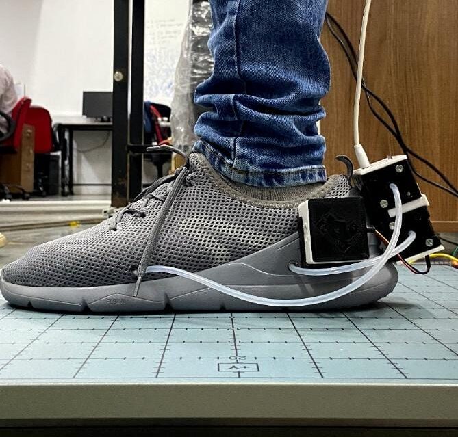
Hardware Implementation: I designed an insole equipped with sealed silicon tube coils connected to Sparkfun Qwiic Micropressure sensors. These coils, serving as pressure pads, were strategically positioned at four regions beneath the feet: [i] Toe, [ii] Metatarsophalangeal 1-2, [iii] Metatarsophalangeal 3-4, and [iv] Heel. The components, including a Portenta H7 microcontroller, a 4-channel multiplexer multiplexer, a 3.3V SD card module, and an ICM-20948 9-dof IMU (located at the heel), were interlinked to record system data and perform real-time predictions. All these electronic elements were housed within a 3D-printed casing, seamlessly integrated at the back of the shoe.
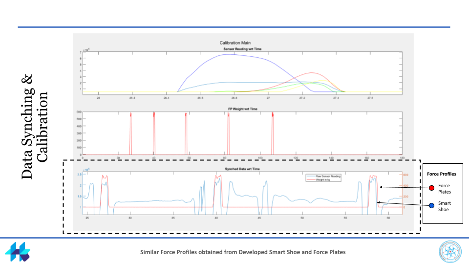
Data Acquisition & Validation: Data collection involved gathering information from five subjects performing walking bouts at varying speeds while wearing the Smart Shoe and walking on the Force Plates, and the recorded sensor readings (including pressure and IMU data from the Smart Shoe) were saved with the ground truth data from the AMTI Force Plates (Max. capacity Fz: 1112N). The raw sensor values were processed to eliminate drift and saturation. I established a data acquisition system (refer to the figure in Additional Documents) to capture sensor readings concurrently with IMU data and force plate acting as the ground truth. Employing a myRIO controller for communication and triggering, and utilizing the VICON nexus as the hub for synchronization, we integrated the Smart Shoe and Force Plates systems.

The sensor operation (for generating pressure map and logging data) code I developed in Arduino IDE can be found below:
#include "ICM_20948.h"
#include<Wire.h>
#include <SD.h>
#include <SparkFun_MicroPressure.h>
//#include "MicroFlow.h"

#define AD0_VAL 1

int prev_time = 0;

float accX, accY, accZ, gyroX, gyroY, gyroZ;
float s1, s2, s3, s4, s = 0;

#define PCAADDR 0x70

SparkFun_MicroPressure mpr1;
SparkFun_MicroPressure mpr2;
SparkFun_MicroPressure mpr3;
SparkFun_MicroPressure mpr4;

ICM_20948_I2C myICM; // Otherwise create an ICM_20948_I2C object

void pcaselect(uint8_t i) {
  if (i > 3) return;

  Wire.beginTransmission(PCAADDR);
  Wire.write(1 << i);
  Wire.endTransmission();
}

// SD Card Config +++++++++++++++++++++++++++++++++++++++++++++++++++++++++++++++++++++++++++++++++++++++++++++++

#define FILE_BASE_NAME "DATA"

File file;                                                                                          // Chip Select Pin
int cs_pin = 7;                                                                                    // initialize file name, plus a null terminator
int count = 0;
char fileName[22] = FILE_BASE_NAME "00.csv";
float cTime;


int avg_size = 100;
static int baseline_value_1;
static int baseline_value_2;
static int baseline_value_3;
static int baseline_value_4;

int current_value_1 = 0;
int current_value_2 = 0;
int current_value_3 = 0;
int current_value_4 = 0;
int offset_value_1;
int offset_value_2;
int offset_value_3;
int offset_value_4;
float final_value_1, final_value_2, final_value_3, final_value_4;

//MicroMLP mlp(layers, topology, weights, biases, RELU);

void setup(){

  Wire.begin();
  Serial.begin(2000000);


   // Blink Portenta LED Yellow ++++++++++++++++++++++++++++++++++++++++++++++++++++++++++++++++++++++++++++++++++++

  digitalWrite(LEDR,LOW);
  digitalWrite(LEDG,LOW);
  digitalWrite(LEDB,HIGH);

  // Reading Average Baseline Pressure Values ---------------------------------------------------------------------------------------------------------------------------------------------------


  baseline_value_1 = 0;
  baseline_value_2 = 0;
  baseline_value_3 = 0;
  baseline_value_4 = 0;

  //Serial.println("Done averaging baseline values...");


  #ifdef USE_SPI
  SPI_PORT.begin();
#else
  Wire.begin();
  Wire.setClock(400000);
#endif

  bool initialized = false;
  while (!initialized)
  {
#ifdef USE_SPI
    myICM.begin(CS_PIN, SPI_PORT, SPI_FREQ); // Here we are using the user-defined SPI_FREQ as the clock speed of the SPI bus
#else
    myICM.begin(Wire, AD0_VAL);
#endif
    Serial.print(F("Initialization of the sensor returned: "));
    Serial.println(myICM.statusString());
    if (myICM.status != ICM_20948_Stat_Ok)
    {
      Serial.println("Trying again...");
      delay(500);
    }
    else
    {
      initialized = true;
    }
  }
  Serial.println("Device connected!");
  myICM.swReset();
  if (myICM.status != ICM_20948_Stat_Ok)
  {
    Serial.print(F("Software Reset returned: "));
    Serial.println(myICM.statusString());
  }
  delay(250);
  myICM.sleep(false);
  myICM.lowPower(false);

  myICM.setSampleMode((ICM_20948_Internal_Acc | ICM_20948_Internal_Gyr), ICM_20948_Sample_Mode_Continuous);
  if (myICM.status != ICM_20948_Stat_Ok)
  {
    Serial.print(F("setSampleMode returned: "));
    Serial.println(myICM.statusString());
  }
  // Set full scale ranges for both acc and gyr
  ICM_20948_fss_t myFSS; // This uses a "Full Scale Settings" structure that can contain values for all configurable sensors
  myFSS.a = gpm4; // (ICM_20948_ACCEL_CONFIG_FS_SEL_e) // gpm2 // gpm4 // gpm8 // gpm16
  myFSS.g = dps2000; // (ICM_20948_GYRO_CONFIG_1_FS_SEL_e) // dps250 // dps500 // dps1000 // dps2000
  myICM.setFullScale((ICM_20948_Internal_Acc | ICM_20948_Internal_Gyr), myFSS);
  if (myICM.status != ICM_20948_Stat_Ok)
  {
    Serial.print(F("setFullScale returned: "));
    Serial.println(myICM.statusString());
  }
  // Set up Digital Low-Pass Filter configuration
  ICM_20948_dlpcfg_t myDLPcfg;    // Similar to FSS, this uses a configuration structure for the desired sensors
  myDLPcfg.a = acc_d473bw_n499bw; // (ICM_20948_ACCEL_CONFIG_DLPCFG_e)
                                  // acc_d246bw_n265bw      - means 3db bandwidth is 246 hz and nyquist bandwidth is 265 hz
                                  // acc_d111bw4_n136bw
                                  // acc_d50bw4_n68bw8
                                  // acc_d23bw9_n34bw4
                                  // acc_d11bw5_n17bw
                                  // acc_d5bw7_n8bw3        - means 3 db bandwidth is 5.7 hz and nyquist bandwidth is 8.3 hz
                                  // acc_d473bw_n499bw

  myDLPcfg.g = gyr_d361bw4_n376bw5; // (ICM_20948_GYRO_CONFIG_1_DLPCFG_e)
                                    // gyr_d196bw6_n229bw8
                                    // gyr_d151bw8_n187bw6Serial.print("Initializing SD card...");

  myICM.setDLPFcfg((ICM_20948_Internal_Acc | ICM_20948_Internal_Gyr), myDLPcfg);
  if (myICM.status != ICM_20948_Stat_Ok)
  {
    Serial.print(F("setDLPcfg returned: "));
    Serial.println(myICM.statusString());
  }
  ICM_20948_Status_e accDLPEnableStat = myICM.enableDLPF(ICM_20948_Internal_Acc, false);
  ICM_20948_Status_e gyrDLPEnableStat = myICM.enableDLPF(ICM_20948_Internal_Gyr, false);
  Serial.print(F("Enable DLPF for Accelerometer returned: "));
  Serial.println(myICM.statusString(accDLPEnableStat));
  Serial.print(F("Enable DLPF for Gyroscope returned: "));
  Serial.println(myICM.statusString(gyrDLPEnableStat));
  // Choose whether or not to start the magnetometer
  myICM.startupMagnetometer();
  if (myICM.status != ICM_20948_Stat_Ok)
  {
    Serial.print(F("startupMagnetometer returned: "));
    Serial.println(myICM.statusString());
  }
  Serial.println();
  Serial.println(F("Configuration complete!"));


  // SD Card Setup -------------------------------------------------------------------------------------------------------------------------------------------------------------------------

  pinMode(cs_pin, OUTPUT);
  Serial.print("Initializing SD card...");

  if (!SD.begin(cs_pin)) {

    Serial.println("Card failed, or not present");

    // Blink Portenta LED Red ++++++++++++++++++++++++++++++++++++++++++++++++++++++++++++++++++++++++++++++++++++

    digitalWrite(LEDR,LOW);
    digitalWrite(LEDG,HIGH);
    digitalWrite(LEDB,HIGH);
    float startTime = millis();
    while (1);

  }

  const uint8_t BASE_NAME_SIZE = sizeof(FILE_BASE_NAME) - 1;

  Serial.println("card initialized.");
  while (SD.exists(fileName))
  {
      if (fileName[BASE_NAME_SIZE + 1] != '9')
      {
        fileName[BASE_NAME_SIZE + 1]++;
      }
      else if (fileName[BASE_NAME_SIZE] != '9')
      {
        fileName[BASE_NAME_SIZE + 1] = '0';
        fileName[BASE_NAME_SIZE]++;
      }
      else
      {
        Serial.println("Can't create file name");

        // Blink Portenta LED Red ++++++++++++++++++++++++++++++++++++++++++++++++++++++++++++++++++++++++++++++++++++

        digitalWrite(LEDR,LOW);
        digitalWrite(LEDG,HIGH);
        digitalWrite(LEDB,HIGH);
      }
  }

  // Opening File and Creating Headers +++++++++++++++++++++++++++++++++++++++++++++++++++++++++++++++++++++++++++++++

  file = SD.open(fileName, FILE_WRITE);

  file.print("currTime");                       file.print(",");
  file.print("s1");                             file.print(",");
  file.print("s2");                             file.print(",");
  file.print("s3");                             file.print(",");
  file.print("s4");                             file.print(",");
  file.print("s");                              file.print(",");
  file.print("AccX");                           file.print(",");
  file.print("AccY");                           file.print(",");
  file.print("AccZ");                           file.print(",");
  file.print("GyroX");                          file.print(",");
  file.print("GyroY");                          file.print(",");
  file.print("GyroZ");                          //file.print(",");


  file.println();
  file.close();                                                                                      // Closing File in setup

  Serial.println("s1, s2, s3, s4, s, AccX, AccY, AccZ, GyroX, GyroY, GyroZ");   // Legend for Serial Plot

  pcaselect(0);
    // setup the 1st sensor
  mpr1.begin();

  pcaselect(1);
  // setup the 2nd sensor
  mpr2.begin();

  pcaselect(2);
  // setup the 3rd sensor
  mpr3.begin();

  pcaselect(3);
  // setup the 4th sensor
  mpr4.begin();

  for (int i = 0; i < avg_size; i++){

       baseline_value_1 += mpr1.readPressure();
       baseline_value_2 += mpr2.readPressure();
       baseline_value_3 += mpr3.readPressure();
       baseline_value_4 += mpr4.readPressure();

     }

  baseline_value_1 /= avg_size;
  baseline_value_2 /= avg_size;
  baseline_value_3 /= avg_size;
  baseline_value_4 /= avg_size;

  delay(5000);

}


void loop(){

  count = count + 1;
  file = SD.open(fileName, FILE_WRITE);                                                             // Opening the File in Loop

  if(count%2 == 1)
  {
    // Blink Portenta LED Magenta ++++++++++++++++++++++++++++++++++++++++++++++++++++++++++++++++++++++++++++++++++++

    digitalWrite(LEDR,LOW);
    digitalWrite(LEDG,HIGH);
    digitalWrite(LEDB,LOW);
  }

  else{

    // Blink Portenta LED Green ++++++++++++++++++++++++++++++++++++++++++++++++++++++++++++++++++++++++++++++++++++++

    digitalWrite(LEDR,HIGH);                                        // Blink Portenta Red Light
    digitalWrite(LEDG,LOW);                                         // Blink Portenta Green Light
    digitalWrite(LEDB,HIGH);                                        // Blink Portenta Blue Light
  }

  // Data Saving Loop -------------------------------------------------------------------------------------------------------------------------------------------------------------------

  float startTime = millis();
  float loopTime = millis();
  while ( ((millis() - startTime)/1000) <= 20){

  cTime = (millis() - startTime);

  if (myICM.dataReady())
    {
      myICM.getAGMT();              // The values are only updated when you call 'getAGMT'
      gyroX = myICM.gyrX();   gyroY = myICM.gyrY();   gyroZ = myICM.gyrZ();
      accX  = myICM.accX();   accY  = myICM.accY();   accZ  = myICM.accZ();
    }

   //X_norm = (X - X_min) / (X_max - X_min)

  pcaselect(0);

  current_value_1 = 0;
  current_value_2 = 0;
  current_value_3 = 0;
  current_value_4 = 0;

  current_value_1 = mpr1.readPressure();
  //Serial.print(" KPa_1     ");

  pcaselect(1);

  current_value_2 = mpr2.readPressure();
  //Serial.print(" KPa_2     ");

  pcaselect(2);

  current_value_3 = mpr3.readPressure();
  //Serial.print(" KPa_3     ");

  pcaselect(3);
  current_value_4 = mpr4.readPressure();
  //Serial.println(" KPa_4");


  // +++++++++++++++++++++++++++++++++++++++++++++++++++++++++++++++++++++++++++++++++++++++++++++++++++++++++++++++
//
//  final_value_1 = constrain(current_value_1, offset_value_1, 16777216);
//  final_value_2 = constrain(current_value_2, baseline_value_2+offset_value_2, 16777216);
//  final_value_3 = constrain(current_value_3, baseline_value_3+offset_value_3, 16777216);
//  final_value_4 = constrain(current_value_4, baseline_value_4+offset_value_4, 16777216);

  s1 = constrain(current_value_1 - baseline_value_1, 50000, 16777216);
  s2 = constrain(current_value_2 - baseline_value_2, 50000, 16777216);
  s3 = constrain(current_value_3 - baseline_value_3, 50000, 16777216);
  s4 = constrain(current_value_4 - baseline_value_4, 50000, 16777216);

  s = (s1 + s2 + s3 + s4)/4;

// Sensor Placement Description
// s1 = Heel; s2 = Meta45 (Foot Outside); s3 = Toe; s4 = Meta12 (Foor Inside);


//   s2        s4
//   s1        s3

  Write_SDcard();

  Serial.print(s1);
  Serial.print("  "); Serial.print(s2); Serial.print("  "); Serial.print(s3); Serial.print("  "); Serial.print(s4); Serial.print("  "); Serial.println(s);

  Serial.print("  ");

  }

    // ----------------------------------------------------------------------------------------------------------------------------------------------------------------------------------

    file.close();                                                                               // Closing File in Loop

   // -----------------------------------------------------------------------------------------------------------------------------------------------------------------------------------

}


void Write_SDcard()
{
  if (file){

    file.print((cTime));                  file.print(",");

    file.print((s1));                     file.print(",");
    file.print((s2));                     file.print(",");
    file.print((s3));                     file.print(",");
    file.print((s4));                     file.print(",");
    file.print((s));                      file.print(",");

    file.print((accX));                   file.print(",");
    file.print((accY));                   file.print(",");
    file.print((accZ));                   file.print(",");
    file.print((gyroX));                  file.print(",");
    file.print((gyroY));                  file.print(",");
    file.print((gyroZ));                  //file.print(",");

    file.println();                       //End of Row move to next row

  }

}
Model Training & Deployment: The distribution of the logged data was examined after normalizing the features to ensure consistency in scale. A correlation study was conducted on the features before they were split for use as training data to train a simple Multi-Layer Perceptron (Architecture: [13, 16, 16, 16, 16, 1]) in Python. The input features included the readings from the six IMU axes, along with the average raw pressure sensor reading. Subsequently, the quantized model weights and biases were exported and transferred using the MicroFlow library for on-board inference on the Portenta H7 to predict real-time output.
Results & Discussion
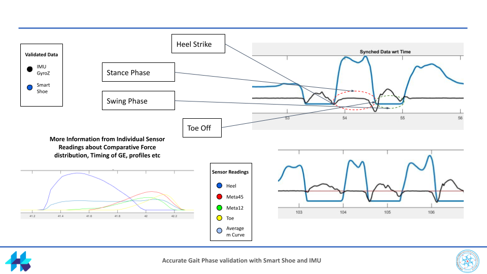
The wireless Smart Shoe system, designed for real-time prediction of Ground Reaction Forces (GRF), demonstrated robust performance during validation against gold standard Force Plates and the VICON motion capture system. The depicted graphs exhibit Smart Shoe readings in compared with Force Plates and IMU data. A distinct M-shaped curve for the GRF, a characteristic of walking, is evident in both systems, with similar force profiles aligning visually throughout the gait cycles. Additionally, the IMU aids in validating temporal gait parameters. Following initial validation, a study involving five healthy and five elderly participants with Parkinson’s disease was conducted to assess GRF variations across diverse terrains. Statistical analysis highlighted significant differences in pressure distribution and force cycles for the elderly group compared to the healthy cohort, providing valuable insights into the experimental results. Result presentation for experiment: TODO.
Conclusion & Future Work
In conclusion, the developed wireless and portable system, featuring the Smart Shoe, has shown potential proving effective in real-time prediction of Ground Reaction Forces (GRF). The hardware implementation, featuring an innovative insole with sealed silicon tube coils and connected sensors, effectively captured and processed nuanced foot dynamics. Data acquisition from subjects performing walking bouts showcased the system’s ability to record diverse gait patterns and speeds, ensuring its versatility for various applications. Future endeavors could explore expanding the participant pool and conducting more extensive studies to enhance the system’s robustness across diverse demographics. Further refinements in the machine learning model, considering additional features or optimizing the existing architecture, could lead to improved prediction capabilities. Additionally, integrating real-time feedback mechanisms or interventions based on the predicted GRF could enhance the system’s utility in rehabilitation and assistive contexts, which is what I am currently working on. Overall, the project lays a foundation for future innovations in the intersection of wearable technology, machine learning, and biomechanics.
Additional Documents
Data Acquisition System | Smart Shoe Testing | CAD Model
Guide: Vineet Vashista | Collaborators: Dhyey Shah