Dual Mode HVAC
Twin Fan Controller System
Introduction
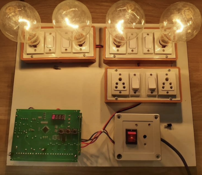
As a part of my final year Comprehensive Project at Embisol Technologies, I worked to develop and test a HVAC Embedded Twin fan Controller as a redundant back up system for large infrastructures and commercial spaces (like Shopping Malls etc) using the PIC 16F1939 Microchip Microcontroller. Offering diverse operational modes, the system was integrated into vented air conditioner systems to guarantee optimal efficiency and fault detection during extended periods of operation. This not only provides clear indications of potential issues but also functions as a backup mode to address problems effectively.
Methodology
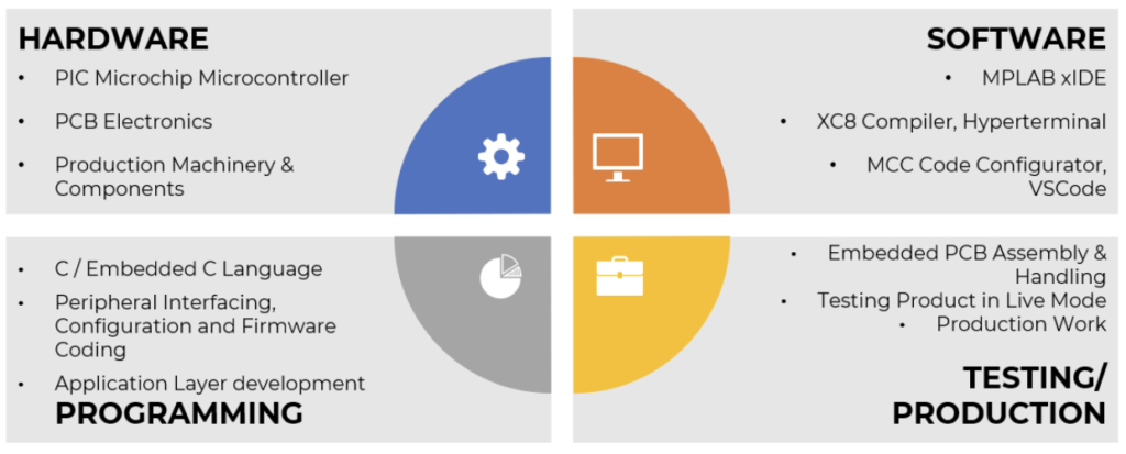
Hardware: The embedded system employed the versatile 8-bit PIC 16F1939 Microchip Microcontroller (Pin Diagram can be found in Additional Documents section below). As a member of member of Microchip’s extreme low power microcontroller family, its special features supporting its choice included an Enhanced Mid-range Core with 49 Instruction, 16 Stack Levels, 96 LCD segment drive support, 32MHz Internal oscillator, 16384 bytes of Program Memory, 1GB RAM and 256 bytes of EEPROM, 14 Channel 10b ADC with Voltage Reference, Four 8-bit Timers (TMR0/TMR2/TMR4/TMR6), One 16-bit Timer (TMR1), with an operating Voltage range of 1.8V – 5.5V. Th external electronic components according to the device design and requirements including resistors, capacitors, relays, switches and indicator LEDs along with the WCS 2720 Hall effect sensor were all assembled on a single PCB according to the deign using the SMT pick and place NeoDen Machine.
Working Methodology: A cooling system including redundant fan controllers. The cooling system includes a first fan controller coupled to control a first plurality of fans and a second fan controller coupled to control a second plurality of fans. Both sets of fans operate simultaneously, and each controller is designed to monitor and identify failures. Upon detecting a failure in the first set, the second controller increases the speed of the corresponding fan in the second set. Additional user-requested features include automatic switching timers and customizable system settings based on the current environment.
#include <xc.h>
#include "tmr0.h"
#include "io.h"
#include "Global.h"
/**
 Section: Global Variables Definitions
*/
TIMER_DATA timer;
SYSTEM_DATA system;
volatile uint8_t timer0ReloadVal;
void (*TMR0_InterruptHandler)(void);
/**
 Section: TMR0 APIs
*/
void TMR0_Initialize(void)
{
 // Set TMR0 to the options selected in the User Interface
 // PSA assigned; PS 1:16; TMRSE Increment_hi_lo; mask the nWPUEN and INTEDG bits
 OPTION_REG = (uint8_t)((OPTION_REG & 0xC0) | (0xD3 & 0x3F));
 // TMR0 6;
 TMR0 = 0x06;
 // Load the TMR value to reload variable
 timer0ReloadVal= 6;
 // Clear Interrupt flag before enabling the interrupt
 INTCONbits.TMR0IF = 0;
 // Enabling TMR0 interrupt

 INTCONbits.TMR0IE = 1;
 // Set Default Interrupt Handler
 TMR0_SetInterruptHandler(TMR0_DefaultInterruptHandler);
}
uint8_t TMR0_ReadTimer(void)
{
 uint8_t readVal;
 readVal = TMR0;
 return readVal;
}
void TMR0_WriteTimer(uint8_t timerVal)
{
 // Write to the Timer0 register
TMR0 = timerVal;
}
void TMR0_Reload(void)
{
 // Write to the Timer0 register
 TMR0 = timer0ReloadVal;
}
void TMR0_ISR(void)
{
 static volatile uint16_t CountCallBack = 0;
 // Clear the TMR0 interrupt flag
 INTCONbits.TMR0IF = 0;
 TMR0 = timer0ReloadVal;
 // callback function - called every 1000th pass
 if (++CountCallBack >= TMR0_INTERRUPT_TICKER_FACTOR)
 {
 // ticker function call
 TMR0_CallBack();
 // reset ticker counter
 CountCallBack = 0;
 }
 // add your TMR0 interrupt custom code
 if(timer.msTMR1) timer.msTMR1--;
 if(timer.adcTMR) timer.adcTMR--;
 if(timer.swdbncTMR) timer.swdbncTMR--;
}

void TMR0_CallBack(void)
{
 // Add your custom callback code here
 //if(system.startFunc) PWM_TOGGLE();
 if(timer.secTMR1) timer.secTMR1--;
 if(timer.secTMR2) timer.secTMR2--;
 if(system.startFunc){
 if(timer.airswTMR) timer.airswTMR--;
 if(timer.currentTMR) timer.currentTMR--;
 if(system.fan1Fault) LED_FAN1_TOGGLE();
 if(system.fan2Fault) LED_FAN2_TOGGLE();
 }
 //if(system.hrTMR){if(timer.minTMR != (system.hrTMR*60)) timer.minTMR++;}
 if(timer.secTMR3 != 59) timer.secTMR3++; else {
 timer.secTMR3 = 0;
 if(system.hrTMR){if(timer.minTMR != (system.hrTMR*60)) timer.minTMR++;}
 }
 if(TMR0_InterruptHandler)
 {
 TMR0_InterruptHandler();
 }
}
void TMR0_SetInterruptHandler(void (* InterruptHandler)(void)){
 TMR0_InterruptHandler = InterruptHandler;
}
void TMR0_DefaultInterruptHandler(void){

}
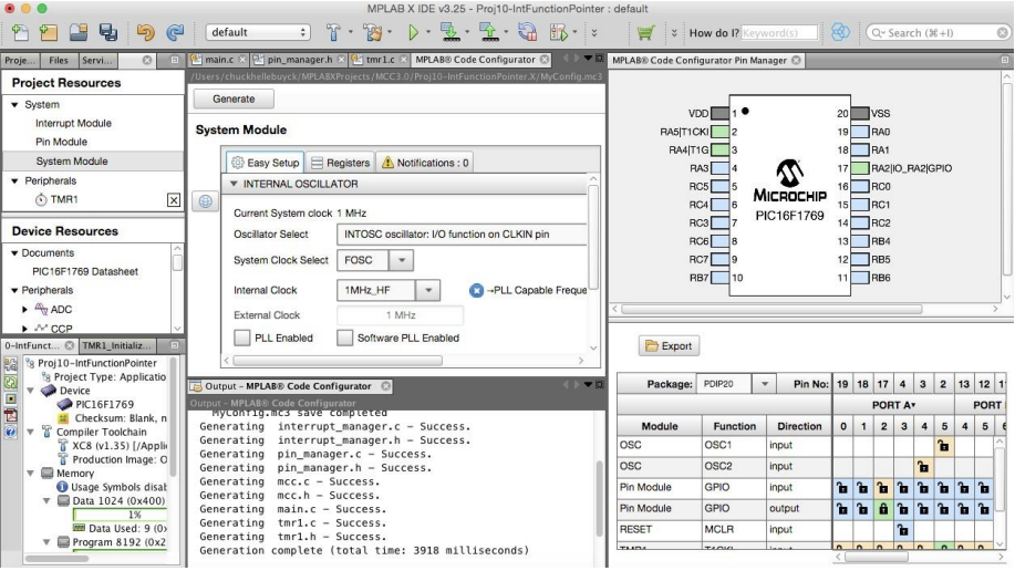
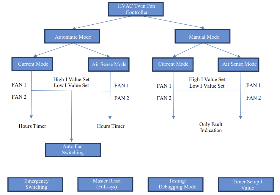
Software Development: The software was programmed in the MPLAB IDE and the X8 compiler using the PICkit 3 programmer. The MCC code configurator enabled the generating of driver codes through GUI. All of the peripherals were programmed as per the following logic: The system offers two primary operational modes: Automatic and Manual. The Automatic Mode enables users to set thresholds, detects faults, initiates automatic panel indication, and uses a timer for efficient fan switching. In Manual Mode, fault indication occurs, but automatic switching is not triggered, allowing human inspection when necessary. Following the initial classification, users can choose between Current Mode and Air Sense Mode for fault detection. Current Mode relies on user-input thresholds for switching, while Air Sense Mode uses a mechanical flap in the air ducts to detect airflow. Additional system modes include Emergency Switching for unknown faults, Master Reset for a full system reset, and a Testing and Debugging Mode. The latter guides users through sequential testing steps, ensuring thorough examination of operational features, real-time load testing, and hardware connection stability testing. This user-friendly approach enhances debugging and application ease.
Results & Discussion
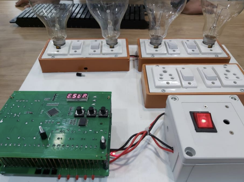
The HVAC board was developed with a Test/Debugging Mode which automatically guides the used through a number of guided steps to auto check and proceed through its performance. This test mode consists of testing of various peripherals, working under no-load and different quantity of loads, switching and indication actions, input value actions etc. Hence the boards were setup on the configured set and tested for correct hardware and software configurations and setups before finally packing them to their product version. After the checking of terminals, correct code uploading and connections the board was dispatched, if any board is found to misbehave or not function properly in the test run-through, the master reset or other modes of operation are tried before checking it for issues and debugging manually before proceeding
Conclusion & Future Work
To summarize the Comprehensive Project, The HVAC Twin Fan Controller developed proved to be a device of vital use in commercial and industrial area in the recent times of Automation and are majorly used to ensure the System safety to the best of the abilities. The device provides the end user with a large variety of options to control the fan flow and ensure safe and sound operation of the AC cooling system and hance leads to an increase of operating life of the system in general, saving long term costs for the industries/users. The device provides the end user with a large variety of options to control the fan flow and ensure safe and sound operation of the AC cooling system and hance leads to an increase of operating life of the system in general, saving long term costs for the industries/users.
Additional Documents
Pin Diagram | The complete code files for the system can be found here: Code File.
Guide: Nirav Karelia (University Guide), Kuldeep Sanchania (Industry Guide)